Moisture Migration
Restricting or controlling water whether it’s a gas, liquid, or solid state is a critical concern in the design of the exterior envelope. Minimizing the potential for water collecting within a stud cavity is the issue. It will degrade any moisture sensitive building material, and reduce the performance of the wall. While stopping water in its liquid and solid state seems straight forward, the gas or vapor state is a little more elusive, but equally important to understand. This section will focus on moisture, water in its gas state, and migration. A review of the ideal gas laws will start the discussion, which will lay the foundation for what drives moisture through wall construction. The next point will cover the concept of vapor permeance and its application in the design of exterior walls. The final item will be on how water and air barriers help control moisture migration.
Principals of Moisture Migration
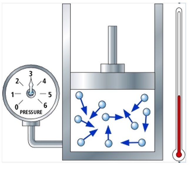
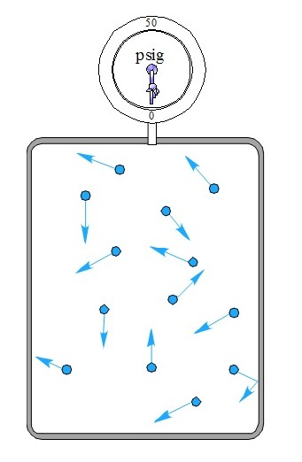 The first concept to consider is that of vapor pressure. A gas of any composition will exhibit a certain pressure. This pressure is caused by the movement of the elements within the molecule of the gas. This is important to understand for it leads to specific issues within the cavity of a wall. The image on the left depicts a closed vessel, or container that contains some water vapor. On top of the vessel is a gauge for measuring the pressure within the container. The blue dots represent water vapor molecules that by nature do not stand still. This movement creates the pressure that will be indicated by the gauge reading. This pressure is very small relative to the pressure experienced with the movement of the air, and set at zero.
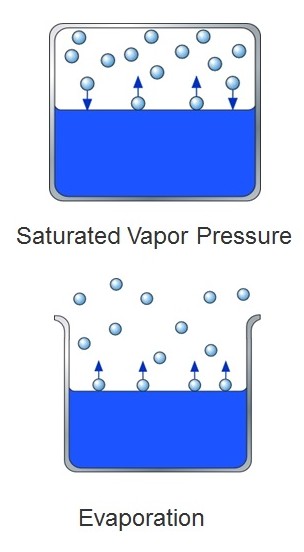 Another important concept is that of saturated vapor pressure. In the graphic on the right are two containers, one is open to the atmosphere while the other is closed. As water molecules move around in the liquid state, some molecules escape the container and become vapor molecules in the atmosphere. The commonly recognized term for this incidence is evaporation. Since it takes energy for evaporation to occur, it stands to reason as you increase the energy, the rate of evaporation increases.
In a closed environment some the water vapor goes back into a liquid state. Saturation occurs when the molecules leaving and entering the liquid state are the same. It is important to control this saturation pressure for it can be the cause of collecting water in its liquid state within a stud cavity.
Water vapor moves from areas of high vapor pressure to areas of less pressure. As in the case of heat transfer, water vapor moves from areas that are warm to those areas that are cold. Therefore, in the case of a wall, the vapor pressure will move from the hot, humid air found in the summer time on the outside to the cooler, dryer temperature on the inside of the building. This means that water vapor is being driven though the wall cavity.
The ideal gas laws will provide insight into why this naturally occurring movement must be controlled through the exterior envelope. The first law to consider is Boyle’s Law. As mentioned earlier, the movement of gas molecules creates a pressure in a closed environment. 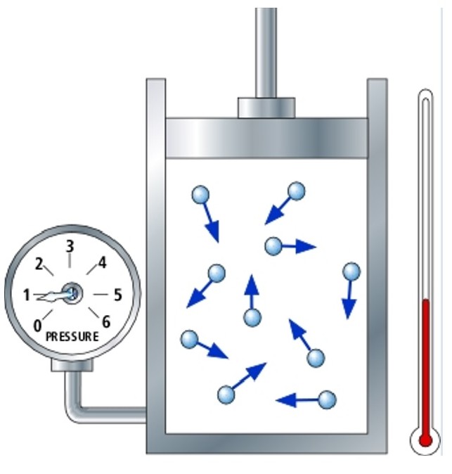 Boyles Law states that the pressure of the gas is related to the volume of the closed container. Moving from one condition to another, such as increasing the volume will impact the pressure of the gas. This is illustrated in the images shown here. There are closed cylinders where the temperature, volume, and pressure can be modified and monitored. The blue dots are showing water molecules that are moving within the closed cylinder. The volume, temperature, and pressure in image one illustrate the first condition.
 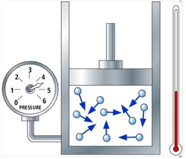 Respecting the Boyle’s Law, mathematically known as P1V1 = P2V2, means that if there is a change in one parameter such as the volume from condition one to two, it will impact pressure. In this example, the volume is greatly reduced thereby increasing the pressure. Following the mathematics, if the pressure volume in condition 1 is a unit of 1, and if the volume is then reduced to one-half in condition 2, the pressure must double. For that to occur the temperature must remain constant.
 Charles’ Law takes the gas laws another step. It also links temperature, volume, and pressure. In this case pressure remains constant. Mathematically this is V1/T1 = V2/T2. Volume increases as temperature increases. Using the same concept as before, if in condition 1 both temperature and volume are a unit of one,
  then when temperature becomes 2 in the second condition so must the volume. This has a practical application with the design and construction of the exterior envelope.
Water within a wall while in a vapor state is not a prelude to wall failure. However, water in its liquid state can pose a very serious threat to the overall performance of either a wood or steel-framed exterior wall. The ideal gas laws explain what happens to water vapor as temperature, volume, and pressure are changed. Prior to this, was a discussion on saturated vapor pressure, which is that pressure where water passes equally between a vapor and a liquid state. Therefore, the goal in design is to keep water in its vapor state below the saturated pressure where it can quickly change to liquid water.
There is a limit to how much moisture (water) can be held in a molecule of air. 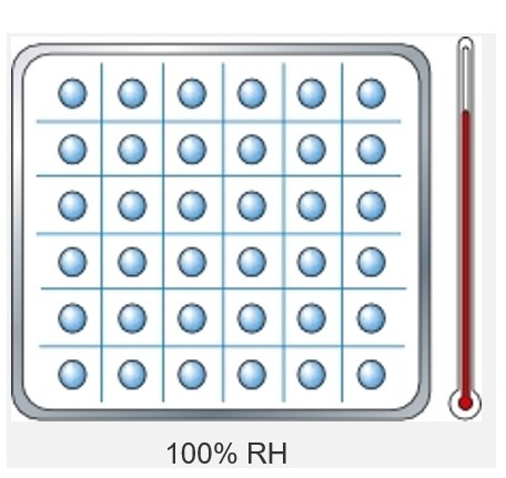 The illustration shows a molecule of air, where the blue grid inside reveals the capacity for the air to hold water. Each blue dot is a water molecule. This ability to hold moisture is temperature dependent. As the temperature drops the amount of water that the air can hold drops as well. Relative humidity is the amount of moisture in the air compared to the maximum the air can hold at a given temperature.
 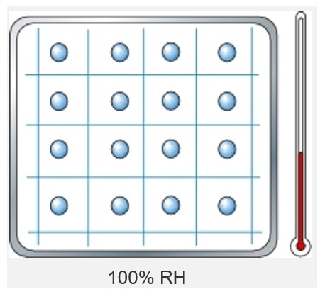 Therefore, in the illustration to the left since every square is filled with moisture the relative humidity is 100%. When the temperature is dropped as in the picture to the right the capacity to hold moisture drops as well. In both cases the relative humidity is still 100%, but the temperature and capacity are vastly different.
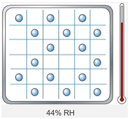 The next step in this evaluation is to view the more normal occurrence. In this graph not every square has moisture in it. When comparing the actual moisture content to the maximum theoretical the air is said to have a 44% relative humidity.
The dew point is the temperature at which the relative humidity is 100%. That essentially means that the air at that temperature can hold no more water. If the surfaces adjacent to the air that has more moisture than it can hold, the air becomes supersaturated. If the adjacent surfaces are lower in temperature, the water vapor changes state to a liquid or condenses on that cooler surface. The actual vapor pressure at any point within a wall assembly is controlled by the material’s permeability. Saturated (100% RH) pressure is controlled by temperature. In exterior envelope wall design it is important to understand where that dew point can fall given the environmental conditions and building materials that are used.
The application of the principals mentioned above can be illustrated with the brick veneer exterior wall shown here. Heat transfer is from warm to cold, and the vapor drive is from warm moist air to colder drier air. 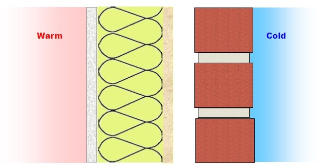 This means that in this example the moisture is being driven from the inside to the outside. Warm moist air is entering the cavity from inside the structure to the outside. The temperature within the cavity is dropping based on the thermal resistance of the various building materials.
As the air gets colder within the cavity it loses its ability to hold moisture. At some point, the dew point temperature may be reached meaning that the air will lose the capability to hold any more water. That means that the air has reached its saturated vapor pressure. If the adjacent building materials are warmer, then the air molecule nothing will happen except the air becomes supersaturated. If the dew point occurs near a building material that is colder in temperature, then condensation occurs. The worst case for this condensation to occur would be up against the exterior sheathing, and inside the stud cavity.
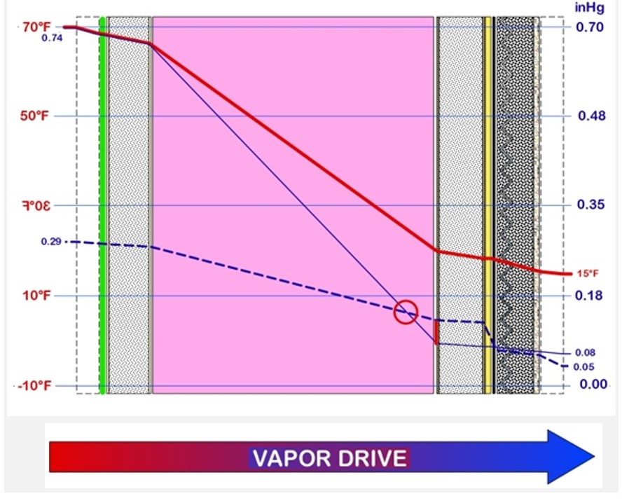 The graphic representation on the left is a cross-section of a cold-formed steel framed exterior wall with stucco on the outside and gypsum board on the inside. The solid red line through the wall shows the temperature at any point through the wall. This temperature gradient is based on the indoor and outdoor temperatures and the thermal resistance of all the components within the wall. The solid blue line through the wall is the saturated pressure based on the temperature at that point. Notice how the solid blue line drops reflecting the ability of the air to hold water vapor is dropping. The dotted blue line depicts the actual condition based on the indoor moisture content. Where the two blue lines cross is the dew point and is the cause for concern. The next colder material, which in the case would be the exterior sheathing will be a site for condensation to occur.
One method that is available to eliminate the potential for condensation in the stud cavity is to minimize the amount of water vapor that is allowed to enter the cavity. The less water vapor that is in the stud cavity the less the chance of reaching a dew point temperature. Some materials allow for the passage of more vapor through the material itself than others. By thoughtfully selecting the building materials that make up the exterior envelope the designer can greatly minimize the potential for a moisture intrusion problem. This leads to a discussion on vapor permeance.
Vapor Permeance
Moisture permeance deals with the ability of water vapor to pass through a material, such as plywood or a sheet of glass. Each building material exhibits a different level of vapor permeance. This is based on the pores within the material itself that allow water to pass through. The range of permeance is from no vapor to all vapor passing through a material. Examples would be a sheet of glass which allows no moisture to a gypsum panel which allows moisture to diffuse though it.
The perm rating of a material is the standard measure of water in a gaseous state will diffuse through the material. The following is taken from the Building in Alaska Document Permeability of Common Building Material to Water Vapor.
If a material has a perm rating of 1.0, we know that in 1 hour, when the vapor pressure difference between the cold side and the warm side of the material is equal to 1 inch of mercury (1" Hg), 1 grain of water vapor will pass through 1 square foot of the material. One grain of water is equal to 1/7000 of a pound.
From this concept the industry has recognized four classes of vapor permeance. They are as follows:
- Vapor impermeable – 0.1 perm or less
- Vapor semi-impermeable - 1.0 perm or less and greater than 0.1 perm
- Vapor semi-permeable - 10 perms or less and greater than 1.0 perm
- Vapor permeable – greater than 10 perms
Traditional design principals were to select a low perm rating on the warm side, with a higher perm rating on the cool side. This is understandable given that warm moist air is driven to a cooler dry area. Envelope design has taken on new importance as we enter into a new era of energy code compliance. A thorough evaluation of climatic conditions on both sides of the exterior envelope and the intended building materials themselves are warranted for successful performance of the wall.
A discussion on exterior envelope is not complete without examining the roles of air and water barriers. They have been in use for decades, but are now mandated by the current energy codes. The water resistive barrier is used for stopping the flow of water in its liquid state and the air barrier can be seen as helping to control water in its vapor state.
Water-Resistant Barriers
Water resistant barriers serve as a second line of defense against moisture (in its liquid state) entering the building. The International Building Code, IBC, has specific language that requires the use of these barriers. In section 1403.2 in the 2012 IBC code, it calls for a “weather-resistant” exterior envelope. This envelope includes the installation of a “water-resistive barrier behind the exterior veneer”. Integral with the barrier is the requirement for flashing to channel any water out of the envelope. Using prescriptive language, the IBC in Section 1404.2 defines the water-resistive barrier (WRB) as “one layer of No. 15 asphalt felt, complying with ASTM D 226 Type 1 felt or other approved materials shall be attached to the studs or sheathing."
The codes allow for alternate materials by showing equivalency in intended performance. The International Code Congress, Evaluation Services (ICC-ES) established an “Acceptance Criteria” to prove required equivalency. Because of alternate materials provision, and the Acceptance Criteria option, there are now several options that are available. The alternates can be divided into three basic categories. They are sheet materials, fluid-applied materials, and certain types of insulating sheathing.
For sheet type materials, the specific Acceptance Criteria is entitled AC 38 Acceptance Criteria for Water-Resistive Barriers. This would include some self-adhered types as well some polyolefin products. Another form of a water-resistive barrier is a fluid applied coating. The Acceptance Criteria that was drafted to show equivalency is AC212 Acceptance Criteria for Water-Resistive Coatings Used as Water-Resistive Barriers over Exterior Sheathing. These materials are usually applied with trowel, brush, or spray applied. When determining the appropriate water-resistive barrier for a project, it is important to make sure the material has the appropriate documentation for its intended application.
Note: The limitations provided here are taken from appropriate building product manufacturer's source. For more and the latest information relative to these limitations, it is recommended to contact either the representative association or a specific building product manufacturer. A partial list of associations, and their links is provided on the home page of this site.
Air Barriers
The 2012 International Energy Conservation Code, IECC, made it mandatory to include an “air barrier” in the exterior envelope. Section C402.4.1 of the code is entitled “Air Barriers”. It states that “a continuous air barrier shall be provided throughout the building thermal envelope”. It does not prescribe on which side (interior or exterior) of the exterior wall that the barrier should be installed. Any joints, seams, and penetrations must be properly sealed.
Two systems are seen as “deemed to comply” and do not require any further air barrier materials. These two systems are:
1. “Concrete masonry walls coated with one application either of block filler and two applications of a paint or sealer coating.”
2. “A Portland cement/sand parge, stucco or plaster minimum 1/2 inch (12 mm) in thickness.”
As in the water barrier there is a prescriptive approach to air barriers. The following list reveals 15 materials that are acceptable for use as an air barrier:
1. Plywood with a thickness of not less than 3/8 inch (10 mm).
2. Oriented strand board having a thickness of not less than 3/8 inch (10 mm).
3. Extruded polystyrene insulation board having a thickness of not less than 1/2 inch (12 mm).
4. Foil-back polyisocyanurate insulation board having a thickness of not less than 1/2 inch (12 mm).
5. Closed cell spray foam a minimum density of 1.5 pcf (2.4 kg/m3) having a thickness of not less than 1-1/2 inches (36 mm).
6. Open cell spray foam with a density between 0.4 and 1.5 pcf (0.6 and 2.4 kg/m3) and having a thickness of not less than 4.5 inches (113 mm).
7. Exterior or interior gypsum board having a thickness of not less than 1/2 inch (12 mm).
8. Cement board having a thickness of not less than 1/2 inch (12 mm).
9. Built up roofing membrane.
10. Modified bituminous roof membrane.
11. Fully adhered single-ply roof membrane.
12. A Portland cement/sand parge, or gypsum plaster having a thickness of not less than 5/8 inch (16 mm).
13. Cast-in-place and precast concrete.
14. Fully grouted concrete block masonry.
15. Sheet steel or aluminum.
For the gypsum panel application there is what is called the “Airtight Drywall Approach” (ADA). This approach is the detailing that is required for using gypsum panels as an air barrier. See the Technical Resource section of this website for more information.
The Air Barrier Association of America, ABAA promotes the concept of an “Air Barrier System”. The system is a series of air movement resistant materials installed in such a way to provide a continuous barrier to air flow. The air barrier system must be seamless across all six sides of the building. The ABAA have a process to evaluate manufacturers’ various assemblies. They also have a training program to certify installers. For more information, one should go to www.airbarrier.org.
Also, as in the case of water barriers, there are alternates that are available for consideration. They fall into two categories, sheet and fluid applied membranes.
Images used are from the AWCI Exterior Envelope – Doing It Right® program and were contributed by participating companies. While reasonable effort has been made to ensure the accuracy of this information, we assume no liability for any errors or omissions on these pages. Please verify all information with the organizations mentioned above.
References
The content of this section was provided by the following entities:
Ares Consulting Services – Phone contact: 301-466-7420
BASF – The Chemical Company
Boyd Consulting Group
CertainTeed Saint-Gobain
DFW Drywall & Acoustical Contractors Association
The Dow Chemical Company
EIFS Industry Members Association
Grupe Gypsum Consulting – Phone Contact: 312.371.7897
Gypsum Association
Henry Company
Icynene, Inc.
Steel Framing Alliance
Steel Framing Industry Association
STO Corporation
USG Corp.
Information sources specific to topics above
Permeability
Permeability of Common Building Material to Water Vapor, EEM-00259, Published by the University of Alaska Fairbanks Cooperative Extension Service.
Water Resistive Barriers
2012 International Building Code, section 1403.2, Section 1404.2, International Code Council
AC38 Acceptance Criteria for Water-Resistive Barriers, ICC Evaluation Service
AC212 Acceptance Criteria for Water-Resistive Coatings Used as Water-Resistive Barriers over Exterior Sheathing, ICC Evaluation Service
Air Barriers
2012 International Energy Conservation Code, Section C402.4.1, International Code Council
Airtight Drywall Approach, Building Science Corp.
Air Barrier Association of America