Heat Transfer
Starting with the earlier definition, the discipline of heat transfer is concerned with only two things, temperature and the flow of heat. This section will delve into both concepts and close with how they impact the exterior framed wall.
Heat
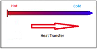
The first step in defining heat transfer is to understand what is heat. Heat, in this context, can be seen as energy in motion. What drives this motion is the differences in temperature within an element. Heat transfer then occurs from an area on that element that is hot to another area that is colder. An example of heat transfer would be the nail shown on the left. Here we see one end of the nail is hot (red in color) and the opposite is cool (blue in color). Heat transfer is that the cool end of the nail will start to get warm as heat is transferred along the length of the nail.
 This is an example of conduction, where heat transfer is through a material. From a mathematical approach the flow of heat through conduction is shown below. Every material has a certain level of thermal conductivity, or the ability to facilitate the passage of heat through the material itself.
 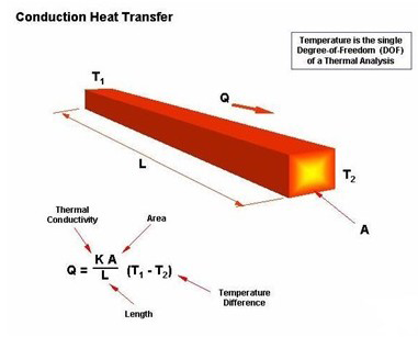 This level of thermal conductivity is expressed as a coefficient in the equation shown here. The point to be made is that the flow of heat is a function of the difference in temperature, the length of the material, the cross-sectional area of the material, and materials ability to transfer heat.
 Heat transfer can also occur in a gas or liquid. This is attributed by the movement of the gas or liquid by the circulation of currents of the medium itself. This is called convection. The image at the left shows the different temperature of the air and its movement away from an object. A common application of that is where a heater placed on one side of the room. Warm air is less dense than cooler air so it rises directly over the heater. The ceiling serves as a barrier to the air. Since the natural drive for heat, remembering that heat is an energy not a temperature reading, is to move from a warmer place to a cooler place. The warm air moves to the opposite, and relatively cooler side of the room. The temperature of the air as it moves across the room is lowered.
 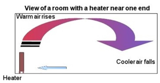 This lower temperature is denser so it tends to drop to the floor area. Thus a cycle of air movement is created simply because of the difference in temperature at different locations within the room.
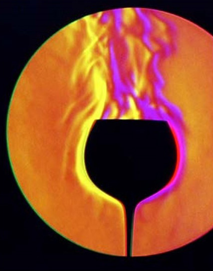
Radiation is the last form of heat transfer. It is considered electromagnetic energy, and is within the infrared spectrum. This energy is transferred in waves. The sun is the earth’s source for warmth, and the method that is used to transfer that heat energy is radiation. 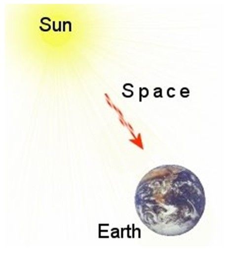 “Thermal radiation is a common synonym for infrared radiation emitted by objects at temperatures often encountered on Earth. Thermal radiation refers not only to the radiation itself, but also the process by which the surface of an object radiates its thermal energy in the form black body radiation. Infrared or red radiation from a common household radiator or electric heater is an example of thermal radiation, as is the heat emitted by an operating incandescent light bulb. Thermal radiation is generated when energy from the movement of charged particles within atoms is converted to electromagnetic radiation.” (Wikipedia).
An interesting phenomenon that is the result of thermal radiation is what is termed “night sky radiation”. Heat energy is absorbed throughout the daylight hours. This absorption occurs in the large sense by the earth itself, but it also occurs with any items of mass, such as a stucco exterior. During the night hours, the temperature differential is inverted, meaning the mass is warmer than the air. The process is then reversed and the energy transfer is in the opposite direction. This explains why heavy mass buildings tend to be cooler during the day, and help warm the space at night. The heat energy is absorbed into the mass and not transferred into the interior of the building during the day. At night the energy is released into the structure, and out into the atmosphere.
Heat Transfer and the Built Environment
All common building materials will conduct heat. Therefore, each building material has a coefficient of conductance (k) value that predicts the amount of energy that the material will conduct. The units for this coefficient are Btu per hour, per square foot of material, per inch thickness of material, per degree Fahrenheit. 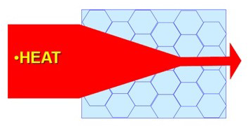 The total heat that will pass through an assembly (the combination of individual building materials each with its own coefficient of conductance) is termed the “coefficient of heat transmission.” This value is expressed as Btu (British Thermal Unit) per hour, per square foot, per the degree Fahrenheit temperature difference between the air on one side of the assembly to the air on the other. This value is called a “U” factor of the assembly. “Thermal resistance” of a material or assembly is the more common term that is used. Mathematically the thermal resistance, “R,” of a material is the reciprocal of its heat transfer coefficient, which is 1/k, 1/C, 1/U. The higher the “R-value” of a material is the greater its resistance to the transfer of heat.
The above is taken from Navigating Uncharted Waters: Understanding the Energy Codes and How They Impact the Role of the Contractor. (A research paper prepared for The Foundation of Wall and Ceiling Industry).
The table below shows the R-value for various common building materials. The R-value is typically given per the given thickness of material. The column that depicts the R-value per inch reveals the relative performance of one material to another.
| Building Material | R-Value | R-Value per Inch |
| 1/2" Plywood | 0.62 | 1.24 |
| 1/2” Gypsum Sheathing | 0.45 | 0.90 |
| 1” EPS Board | 3.80 | 3.80 |
| 3-1/2” Glass-Fiber Batt | 11.00 | 3.14 |
| 1” XPS Board | 5.00 | 5.00 |
| 1” Poliso | 6.50 | 6.50 |
To determine the total resistance for the assembly the individual components of the wall are added up. This includes a column of air on the inside of the wall and an air column on the outside of the wall. The reciprocal of the sum of the thermal resistance is then taken to provide what is called the U-Factor of the assembly.
 In order to predict the thermal performance of a wall the impact of the heat loss through the framing member must be taken into account. The heat transfer through a stud is greater than through a stud cavity. This can be seen in the illustration below. This difference in transfer is evaluated through the following equation. Uw is the U-Factor for the total assembly.
  The R-value of the insulation, Rins, is reduced by a coefficient, Fc, that reflects the presence of the framing. This reduction has been as high as 44% for cold-formed steel framing. This reduction in performance is taken into account in the energy codes and drives the need for continuous insulation.
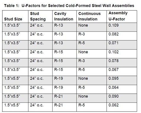 The Steel Framing Alliance has posted the table below that provides U-Factors for various cold-formed steel framed walls. This can be used as a guide for determining design compliance to the energy codes. Further information is in their pamphlet entitled Thermal Design and Code Compliance for Cold-Formed Steel Walls.
References
The content of this section was provided by the following entities:
Ares Consulting Services – Phone contact: 301-466-7420
BASF – The Chemical Company
Boyd Consulting Group
CertainTeed Saint-Gobain
DFW Drywall & Acoustical Contractors Association
The Dow Chemical Company
EIFS Industry Members Association
Grupe Gypsum Consulting – Phone Contact: 312.371.7897
Gypsum Association
Henry Company
Icynene, Inc.
National Gypsum Co.
Steel Framing Alliance
Steel Framing Industry Association
STO Corporation
USG Corp.
Navigating Uncharted Waters: Understanding the Energy Codes and How They Impact the Role of the Contractor, Foundation of the Wall and Ceiling Industry
Thermal Design and Code Compliance for Cold-Formed Steel Walls, Steel Framing Alliance