Exterior System Details - Stucco
The details that follow are standard details that depict proper detailing for cold-formed steel framed exterior walls with a conventional stucco finish. These details are adapted from the concepts provided by the Foam Sheathing Committee (FSC). Another source for these details is from the Western Wall and Ceiling Institute’s pamphlet entitled The Energy Code and Plaster Assemblies. Additional comments came from the Minnesota Lath & Plaster Bureau. The intent is to serve as a guide. Final approval of detailing for a specific construction project is the right and responsibility of the Architect of Record.
CONVENTIONAL STUCCO SOLUTIONS
PARAPET DETAIL
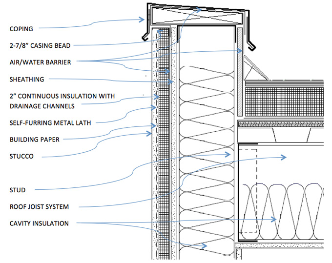
GENERAL NOTES
- Installation of insulation shall meet the requirements of the Foam Sheathing Committee’s Document TER 1205-05 (latest version) Construction Details for the Use of Foam Plastic Insulating Sheathing (FPIS) in Light-Frame Construction.
- Install continuous insulation with fasteners into cold-formed steel framing members. Size, Type, and spacing of fasteners as required by foam insulation manufacturer.
- Continuous Insulation shall be 2” maximum and provide shallow drainage channels per design PWA-104 from the Western Wall and Ceilings Institute.
- Provide air/water barrier compatible to selected finish. Air/water barrier to be continuous from face of exterior wall, over parapet, and onto roof membrane. Details as shown are for self-adhered or fluid-applied non-foaming membranes.
- Check with Underwriters Laboratories for specific air/water barrier systems.
- Although not a code requirement, install building paper between the stucco and the continuous insulation.
- Face of coping shall extend a minimum of 2-1/2” over stucco finish material.
- Stud spacing for stucco is 16” o.c. for stucco. Spacing may go to 24” o.c. if certain provisions of PWA 104 are met.
- Install Cement Plaster, Lath, accessories including control joints in accordance with ASTM C 926 Standard Specification for Application of Portland Cement-Based Plaster and ASTM C 1063 Standard Specification for Installation of Lathing and Furring to Receive Interior and Exterior Portland Cement-Based Plaster.
- Follow SFIA Technical Guide for Cold-Formed Steel Framing Products for specific depth, thickness, and spacing of structural studs and roof joists.
- Consult with specialty structural engineer for structural stud and roof design.
- Check local codes and mechanical engineer for vapor retarder type and location.
WINDOW HEAD DETAIL
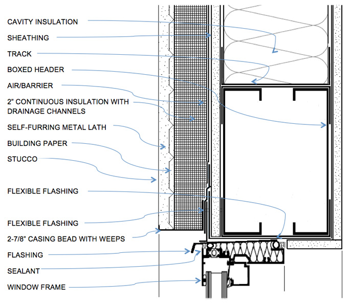
GENERAL NOTES
- Installation of insulation shall meet the requirements of the Foam Sheathing Committee’s Document TER 1205-05 (latest version) Construction Details for the Use of Foam Plastic Insulating Sheathing (FPIS) in Light-Frame Construction.
- Install continuous insulation with fasteners into cold-formed steel framing members. Size, Type, and spacing of fasteners as required by foam insulation manufacturer.
- Continuous Insulation shall be 2” maximum and provide shallow drainage channels per design PWA-104 from the Western Wall and Ceilings Institute.
- Provide air/water barrier compatible to selected finish. Air/water barrier to be continuous. Details as shown are for self-adhered or fluid-applied non-foaming membranes.
- Cavity insulation in boxed header removed for clarity.
- Wrap window rough opening with appropriate flexible flashing material.
- Check with Underwriters Laboratories for specific air/water barrier systems.
- Although not a code requirement, install building paper between the stucco and the continuous insulation.
- Protect corner of interior gypsum panel panels with appropriate corner reinforcement.
- Stud spacing for stucco is 16” o.c. for stucco. Spacing may go to 24” o.c. if certain provisions of PWA 104 are met.
- Install Cement Plaster, Lath, accessories including control joints in accordance with ASTM C 926 Standard Specification for Application of Portland Cement-Based Plaster and ASTM C 1063 Standard Specification for Installation of Lathing and Furring to Receive Interior and Exterior Portland Cement-Based Plaster.
- Follow SFIA Technical Guide for Cold-Formed Steel Framing Products for specific depth, thickness, and spacing of structural studs.
- Consult with specialty structural engineer for structural stud and box header design.
- Check local codes and mechanical engineer for vapor retarder type and location.
WINDOW JAMB DETAIL
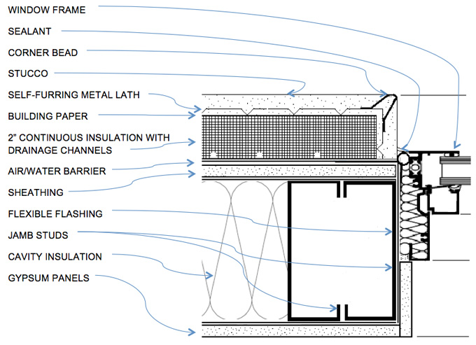
GENERAL NOTES
- Installation of insulation shall meet the requirements of the Foam Sheathing Committee’s Document TER 1205-05 (latest version) Construction Details for the Use of Foam Plastic Insulating Sheathing (FPIS) in Light-Frame Construction.
- Install continuous insulation with fasteners into cold-formed steel framing members. Size, Type, and spacing of fasteners as required by foam insulation manufacturer.
- Continuous Insulation shall be 2” maximum and provide shallow drainage channels per design PWA-104 from the Western Wall and Ceilings Institute.
- Cavity insulation omitted from boxed jamb studs for clarity.
- Provide air/water barrier compatible to selected finish. Air/water barrier to be continuous. Details as shown are for self-adhered or fluid-applied non-foaming membranes.
- Wrap window rough opening with appropriate flexible flashing material.
- Check with Underwriters Laboratories for specific air/water barrier systems.
- Although not a code requirement, install building paper between the stucco and the continuous insulation.
- Protect corner of interior gypsum panel panels with appropriate corner reinforcement.
- Stud spacing for stucco is 16” o.c. for stucco. Spacing may go to 24” o.c. if certain provisions of PWA 104 are met.
- Install Cement Plaster, Lath, accessories including control joints in accordance with ASTM C 926 Standard Specification for Application of Portland Cement-Based Plaster and ASTM C 1063 Standard Specification for Installation of Lathing and Furring to Receive Interior and Exterior Portland Cement-Based Plaster.
- Follow SFIA Technical Guide for Cold-Formed Steel Framing Products for specific depth, thickness, and spacing of structural studs.
- Consult with specialty structural engineer for structural stud and jamb stud design.
- Check local codes and mechanical engineer for vapor retarder type and location.
WINDOW SILL DETAIL
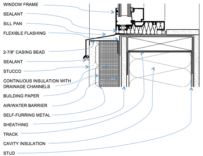
GENERAL NOTES
- Installation of insulation shall meet the requirements of the Foam Sheathing Committee’s Document TER 1205-05 (latest version) Construction Details for the Use of Foam Plastic Insulating Sheathing (FPIS) in Light-Frame Construction.
- Install continuous insulation with fasteners into cold-formed steel framing members. Size, Type, and spacing of fasteners as required by foam insulation manufacturer.
- Continuous Insulation shall be 2” maximum and provide shallow drainage channels per design PWA-104 from the Western Wall and Ceilings Institute.
- Wrap window rough opening with appropriate flexible flashing material.
- Install sill pan with positive drainage to exterior.
- Check with Underwriters Laboratories for specific air/water barrier systems. Details as shown are for self-adhered or fluid-applied non-foaming membranes.
- Although not a code requirement, install building paper between the stucco and the continuous insulation.
- Protect corner of interior gypsum panel panels with appropriate corner reinforcement.
- Stud spacing for stucco is 16” o.c. for stucco. Spacing may go to 24” o.c. if certain provisions of PWA 104 are met.
- Install Cement Plaster, Lath, accessories including control joints in accordance with ASTM C 926 Standard Specification for Application of Portland Cement-Based Plaster and ASTM C 1063 Standard Specification for Installation of Lathing and Furring to Receive Interior and Exterior Portland Cement-Based Plaster.
- Follow SFIA Technical Guide for Cold-Formed Steel Framing Products for specific depth, thickness, and spacing of structural studs.
- Consult with specialty structural engineer for structural stud design.
- Check local codes and mechanical engineer for vapor retarder type and location.
INTERMEDIATE FLOOR, BALLOON FRAME DETAIL
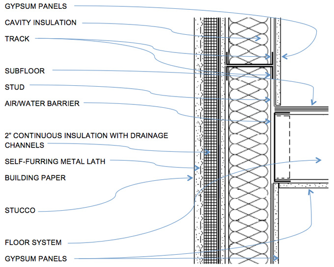
GENERAL NOTES
- Installation of insulation shall meet the requirements of the Foam Sheathing Committee’s Document TER 1205-05 (latest version) Construction Details for the Use of Foam Plastic Insulating Sheathing (FPIS) in Light-Frame Construction.
- Install continuous insulation with fasteners into cold-formed steel framing members. Size, Type, and spacing of fasteners as required by foam insulation manufacturer.
- Continuous Insulation shall be 2” maximum and provide shallow drainage channels per design PWA-104 from the Western Wall and Ceilings Institute.
- Check with Underwriters Laboratories for specific air/water barrier systems. Details as shown are for self-adhered or fluid-applied non-foaming membranes.
- Although not a code requirement, install building paper between the stucco and the continuous insulation.
- Stud spacing for stucco is 16” o.c. for stucco. Spacing may go to 24” o.c. if certain provisions of PWA 104 are met.
- Install Cement Plaster, Lath, accessories including control joints in accordance with ASTM C 926 Standard Specification for Application of Portland Cement-Based Plaster and ASTM C 1063 Standard Specification for Installation of Lathing and Furring to Receive Interior and Exterior Portland Cement-Based Plaster.
- Follow SFIA Technical Guide for Cold-Formed Steel Framing Products specific depth, thickness, and spacing of structural studs and floor system.
- Consult with specialty structural engineer for structural stud/floor system design.
- Check local codes and mechanical engineer for vapor retarder type and location.
FOUNDATION DETAIL
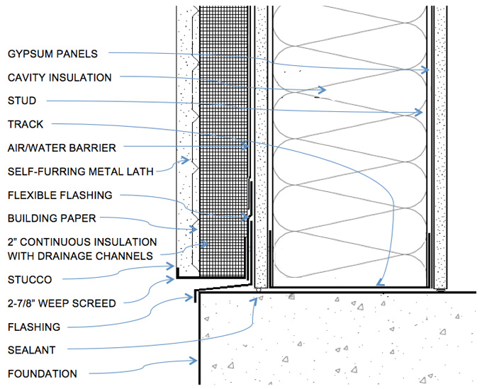
GENERAL NOTES
- Installation of insulation shall meet the requirements of the Foam Sheathing Committee’s Document TER 1205-05 (latest version) Construction Details for the Use of Foam Plastic Insulating Sheathing (FPIS) in Light-Frame Construction.
- Install continuous insulation with fasteners into cold-formed steel framing members. Size, Type, and spacing of fasteners as required by foam insulation manufacturer.
- Continuous Insulation shall be 2” maximum and provide shallow drainage channels per design PWA-104 from the Western Wall and Ceilings Institute.
- Check with Underwriters Laboratories for specific air/water barrier systems. Details as shown are for self-adhered or fluid-applied non-foaming membranes.
- Although not a code requirement, install building paper between the stucco and the continuous insulation.
- Stud spacing for stucco is 16” o.c. for stucco. Spacing may go to 24” o.c. if certain provisions of PWA 104 are met.
- Install Cement Plaster, Lath, accessories including control joints in accordance with ASTM C 926 Standard Specification for Application of Portland Cement-Based Plaster and ASTM C 1063 Standard Specification for Installation of Lathing and Furring to Receive Interior and Exterior Portland Cement-Based Plaster.
- Follow SFIA Technical Guide for Cold-Formed Steel Framing Products for specific depth, thickness, and spacing of structural studs.
- Consult with specialty structural engineer for structural stud system design.
- Check local codes and mechanical engineer for vapor retarder type and location.
- Provide termite separation as required by local code.
- Foundation insulation omitted for clarity. Follow local energy code requirements.
While reasonable effort has been made to ensure the accuracy of this information, we assume no liability for any errors or omissions on these pages. Please verify all information with the organizations mentioned above. It is the right and responsibility for the architect of record to make final material/system selection.