Construction Joints
GENERAL DISCUSSION
 The issue of maintaining the fire resistance as one building system element (wall system) interfaces with another building system element (floor/ceiling system) has been a concern for many years. The established and recognized test standard ASTM E 119 Standard Test Methods for Fire Tests of Building Construction and Materials purposely isolates one building system element from another. In the mid-sixties the Gypsum Association commissioned Underwriters Laboratories to run a series of tests to explore that specific interface of the wall and floor/ceiling. The intent was to determine the effect of what was then called “perimeter relief” of the partition in general, and the differential movement between the floor system and the wall.
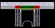 More recently, ASTM E 1966 Standard Test Method for Fire-Resistive Joint Systems was developed to standardize the test procedure thereby allowing testing facilities to list assemblies. The most common version of the joint systems is called “head-of-wall”, and is as described above. The head-of-wall assembly can be considered either static (no differential movement between adjacent systems) or dynamic. An example of the static is shown to the right. The dynamic application allows for differential movement, and in three different classifications. These classifications are ranked as to the number of cycles that the anticipated movement undergoes. There are three different levels of classification. The classifications are ranked by the
 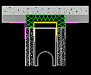 minimum number of cycles and the rate of the cycle (cycles per minute). Each listed dynamic assembly provides the designer with the maximum amount of movement expressed as a percentage of compression or extension that the joint can accommodate. The listing will also disclose the amount of cycling. An example of a dynamic system is illustrated here. The difference between the two types is shown by the gap between the top if the gypsum panels and the bottom of the metal deck. Also, there is a deep leg runner track that allows for the stud to “float”. The gypsum panels of the wall assembly are attached to the stud, not to the runner track. The gap between the top of the gypsum panel and the bottom of the metal deck is filled with a high-melt, non-combustible insulation. A spray coating, typically acrylic, is then applied to both the deck and the wall to seal off the area.
CONTROL JOINTS IN FIRE RESISTIVE ASSEMBLIES
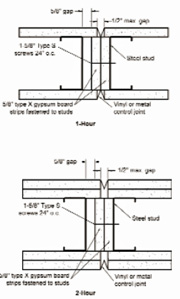 Another question that comes up is how to maintain the fire resistance of a wall when a control joint is required to control gypsum panel movement and minimizing cracking in the gypsum. The Gypsum Association has published some Details in their GA-600 Fire Resistance Design Manual. The details are shown here. The Type X gypsum panels attached to the web of the cold-formed steel stud is to protect against a direct breach of protection thereby creating an avenue for heat transfer. There is data that suggests that without the panels in the cavity there will be a premature failure in fire resistance.
TYPICAL SYSTEM COMPONENTS
Gypsum Wallboard
Composition: A non-combustible gypsum core with fire resistive Type X core, and paper facings.
Size: ½”, 5/8” thick, 4’ wide x 8’ – 14’long
Application: Interior wall and ceilings
 Compliance: ASTM C1396 Standard Specification of Gypsum Board
Limitations:
Avoid exposure to sustained temperatures exceeding 125 ˚F (52 ˚C).
Avoid exposure to excessive, repetitive or continuous moisture before, during and after installation. Eliminate sources of moisture immediately.
The panel is Non-loadbearing.
Installation: GA 216 Application and Finishing of Gypsum Panel Products
Architectural Spec: 09 21 16 Gypsum Board Assemblies
More and Latest Information Link: www.gypsum.org
COLD-FORMED STEEL FRAMING
 Composition: Non-combustible, cold-formed steel galvanized (G40) or equivalent coating to resist corrosion.
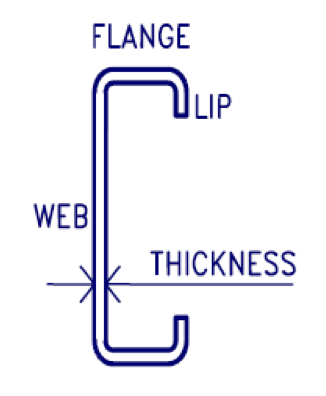
Size: 1-5/8” web x 18 mils thickness to 8” web x 68 mils thickness
Application: Interior Walls, non-structural applications
Compliance: AISI S100 North American Specification for the Design of Cold-Formed Steel Structural Members, steel must comply with ASTM C645 Standard Specification for Steel Sheet for Non-Structural Steel Framing Members. .
Limitations:
Cold-formed steel framing must be laterally braced.
Max. stud spacing is 24 inches on center.
Installation: Per ASTM C754 Standard Specification for Installation of Steel Framing Members to Receive Screw-Attached Gypsum Panel Products, or ASTM C1004 Standard Specification for Installation of Load Bearing (Transverse or Axial) Steel Studs or Related Accessories.
Architectural Spec: 09 22 16.13 Non-structural Metal Stud Framing
More and Latest Information Link: www.steelframingassociation.org
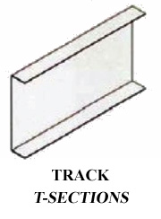
COLD-FORMED STEEL FRAMING DEEP LEG RUNNER
 Composition: Non-combustible, cold-formed steel galvanized (G40) or equivalent coating to resist corrosion.
Size: Stud web depth. Length of leg and steel thickness must be designed per project conditions. This is a proprietary design
Application: Head-of-wall interior walls, non-structural applications
Compliance: AISI S100 North American Specification for the Design of Cold-Formed Steel Structural Members, steel must comply with ASTM C645 Standard Specification for Steel Sheet for Non-Structural Steel Framing Members. .
Limitations:
Length of leg to accommodate anticipated deflection plus stud engagement.
Engineering analysis required to determine steel thickness.
Installation: Manufacturer’s specifications
Architectural Spec: 09 22 16.13 Non-structural Metal Stud Framing
More and Latest Information Link: Manufacturer’s website
MINERAL WOOL INSULATION
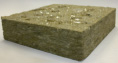 Composition: Non-combustible batts made from rock wool or slag comes with or without foil facing
Size: 16” or 24” wide x 48” long
Application: Installation at gaps between deck and top of gypsum panel and above track and below deck.
Compliance: ASTM C665, Type II, Class C, Category I Standard Specification for Mineral-Fiber Blanket Thermal Insulation for Light Frame Construction or Manufactured Housing
Limitations:
Insulation must be held in place with fasteners or spray acrylic coating.
Insulation should be kept clean and dry at all times.
Installation: Manufacturer’s Installation Guidelines
Architectural Spec: 07 21 16 Blanket Insulation
SPRAY ACRYLIC COATING
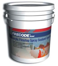 Composition: A single-component, water-based, acrylic sealants used for firestop applications.
Size: 4.5 Gallon Pail
Application: Head-of-wall applications and fire stops
Compliance: Must meet all of the conditions of ASTM E1966, UL 2079, ASTM E84 and CAN4-S115.
Limitations:
Do not apply over damp or contaminated surfaces.
Installation: Manufacturer’s Installation Guidelines
Architectural Spec: 07 84 43 Joint Firestopping
While reasonable effort has been made to ensure the accuracy of this information, we assume no liability for any errors or omissions on these pages. Please verify all information with the organizations mentioned above.
Note: The limitations provided here are taken from appropriate building product manufacturer's source. For more and the latest information relative to these limitations, it is recommended to contact either the representative association or a specific building product manufacturer. A partial list of associations, and their links is provided on the home page of this site.