Fire Resistance
There are four different fire resistive tests that cover wall system design. The main and oldest of the four tests is known as ASTM E119 Standard Test Methods for Fire Tests of Building Construction and Materials. The next two tests concern penetrations and construction joints in a fire resistive wall. The fire test on penetrations is ASTM E814 Standard Test Method for Fire Tests of Penetration Firestop Systems. Construction joints between fire resistive walls are evaluated under ASTM E1966 Standard Test Method for Fire-Resistive Joint Systems. The fourth test was especially developed for exterior walls. Its intent is to measure the impact of foam plastics when used in an exterior wall that will be used on an otherwise non-combustible wall.
ASTM E119 is designed to gauge the ability of various construction elements to maintain their structural integrity while holding a fire to its location of origin. The test procedure covers walls, floors, roofs, beams, and columns. A building element such as a wall is subjected to controlled fire on one side. The wall must not exceed specific temperatures on the surface on the other side. It is meant to measure heat transfer and the transmission of hot gases through the wall itself. If the wall or building element is to be load-bearing, the test will evaluate the wall’s ability to maintain its structural capacity under test conditions (elevated temperatures). The application of a standard fire hose stream may be applied after the fire portion to determine structural integrity.
The test is designed for comparative purposes only. It provides data to illustrate how one type of wall performs compared to another. It is not meant to predict a tested wall’s performance in the event of an actual fire. Also, the test does not provide information as to how the element will perform in sizes other than what was tested. It does not evaluate smoke migration or toxicity. The test only considers elements isolated from the rest of the structure. It does not look at, for example, the intersection of a wall and a floor assembly.
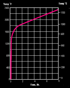
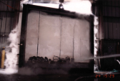
The wall size for a fire test is a nominal 10 foot X 10 foot, or 100 square feet. The wall is built within a steel/concrete frame and then placed in front of the furnace itself. Installation is done in such a way that one side of the partition will be exposed to the fire, and the other side is not. The temperature on the exposed side is closely monitored and controlled. There is a recognized time-temperature curve shown here that must be followed. The temperature within the furnace increases at a very rapid pace, then tapers off with time. Within the first five minutes the temperature will reach be 1000oF, while after 2 hours the temperature will be 2000oF.
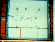
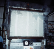
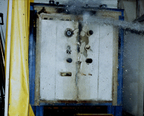
This picture shows the wall to be tested clamped in front of the furnace. Under the nine gray squares are heat measuring devices called thermocouples. The thermocouples are used to measure the unexposed side of the wall. During the test the average temperature at the nine locations cannot exceed 250oF plus ambient (the temperature in the room when the test is started). Also, no single temperature can exceed 325oF plus ambient. The picture on the left is a wall in the middle of a test. You will notice that there appears to be smoke rising from the test specimen. When that is seen, a lab technician is to place what is called “cotton waste” at the location where the smoke is emanating from. Should the cotton char, that indicates the presence of hot gases escaping, and the test is terminated. If the wall system includes gypsum panels, there is a very good chance that what appears to be smoke is simply steam. Gypsum contains chemically combined water that is released as steam at elevated temperatures.
The final part of the test is what is called a hose stream test. Essentially the wall system is rebuilt and fire tested for half the time, but not to exceed one hour, for the intended rating. For example, one hour retest if a two hour wall is to be the desired rating. Immediately after the one hour exposure, the wall is removed from the face of the furnace and subjected to a hose stream of water. This hose stream must be from a 2-1/2 inch hose with a National Standard playpipe nozzle with a 1-1/8 inch tip. This hose stream will be shot from a distance of 20 feet. The duration of the hose stream test will vary with the intended fire rating. For example, a two hour fire rating requires a 2-1/2 minute hose stream exposure, while the one hour fire rating requires a one minute hose stream exposure. To pass this portion of the test, no water can protrude beyond the plane of the wall.
The following links are suggested for more information:
Fire Stops
The previously described test protocol only evaluates the fire resistive performance of building elements such as walls. It is logical to assume that this performance is greatly reduced if there are any penetrations through the wall. There is a specific test procedure for evaluating penetrations. The material that is used to “seal” the penetration is called a “fire stop”. Fire stops should be considered as a system, for in many cases there are several constituents that make up the fire stop. ASTM E814 is the recognized test to evaluate the performance of fire stop systems.
The test follows the same concept as ASTM E119. It uses the same “time-temperature curve” as a control and has a requirement for a hose stream test. The picture shown here is of a hose stream test on a wall specimen that contains several through-penetrations. A fire stop system is specific to the materials in the fire stop, the manner they are installed, the size of hole they fill, and the make-up of the wall or floor in which they are tested. Based on the outcome of the ASTM E814 test, a fire stop system is given two ratings. The first is an “F” rating which indicates, in time, the appearance of flame on the side opposite the fire exposed side. The second is a “T” rating which measures heat transfer in time through the fire stop.
The fire stop test is limited only to walls and floors that have already been tested according to ASTM E119. As with ASTM E119, the test is not intended to predict performance in an actual fire. Also similar to ASTM E119 the test does not evaluate serviceability after a fire test or event.
The following sites are offered for more information:
Head-Of-Wall Fire Resistance
The next type of fire testing looks at how various building elements interface. ASTM E119 is only concerned with individual, isolated building elements. ASTM E 1966 is used to analyze the fire performance at the interface of adjacent fire resistive assemblies. Similar to ASTM E814, this test starts with the same principals as ASTM E119. It shares same time-temperature curve and the same requirements for fire exposure and hose stream. This test evaluates what is termed as a “joint system”. A joint system is a combination of materials that are designed and installed at the interface of two hourly rated (ASTM E119) building elements. The test analyzes the effect of building movement on the ability of a joint system to contain a fire during a predetermined time exposure. The load-bearing capacity of the joint is evaluated as well as the ability of the joint system to impede the passage of flame (heat) and hot gases.
The following sites are offered for more information:
NFPA 285
Building officials became concerned with the proliferation of foam plastics in exterior walls that were being used in otherwise non-combustible buildings. Their concern was how the plastic would affect the vertical spread of a fire up the exterior face of a building. To analyze this impact,
NFPA 285: Standard Fire Test Method for Evaluation of Fire Propagation Characteristics of Exterior Non-Load Bearing Wall Assemblies Containing Combustible Components was drafted. The test calls for a 2-story twenty-four foot tall assembly to be exposed to fire. Each floor is twelve feet tall. During the test, flame spread up the face of the wall is observed. Horizontal flame spread is also evaluated. Flame spread within the cavity of the wall and the inside face of the wall is also measured. A very unique aspect of this test is that it requires fire exposure on both sides of the wall. All the wall panel tests look at fire exposure on one side only, and also measure heat transfer through the walls.
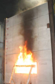
Exterior walls contain windows, and windows are easily breached at elevated temperatures. Glass cannot withstand high temperatures; they will break and fall out in a fire event. When this occurs, the wall is exposed to fire on both sides. This is of critical concern when considering how a wall assembly can contain fire to its floor of origin. The photograph at the left clearly shows the impact that a breached window has on fire containment. This is the unexposed side of the wall and the flames are on what would be the exterior side of a building.
Acoustics
Acoustics in wall system design is important. A special concern is sound transmission loss through the wall. This leads to determining a wall’s Sound Transmission Classification, STC. The laboratory test method for obtaining this classification is ASTM E90 Standard Test Method for Laboratory Measurement of Airborne Sound Transmission Loss of Building Partitions and Elements. Similar to ASTM E119, this test is best used in comparing the performance of different wall systems. It is not intended to predict in-place acoustical performance. Also, as in E119, the wall to be tested is isolated from adjacent systems and the building structure itself. This is important for determining acoustical performance. What are called flanking paths are those paths that allow sound to bypass the wall thus effectively reducing the acoustical performance. Examples of flanking paths are where the wall interfaces structure, placement of doors, and even electrical outlet boxes. The result of not including flanking paths in laboratory test is that the values obtained from a laboratory reflect a “best case” scenario.
The systems that are considered in ASTM E90 include walls, floor-ceilings assemblies, doors, and roofs. Sound travels throughout a building in two ways. The first is sound that travels through the air and is called “airborne.” The second is sound that travels through the structure itself and is called “structure borne.” ASTM E90 only evaluates airborne sound. In the test sound is generated at 16 specific frequencies, starting at 125 hz, or cycles per second and ending at 4000 hz. At each tested frequency the amount of energy is measured in the receiving room is measured. The difference is called the transmission loss, and it is graphically tabulated. When all frequencies have been tabulated and plotted, the STC value can then be graphically determined.
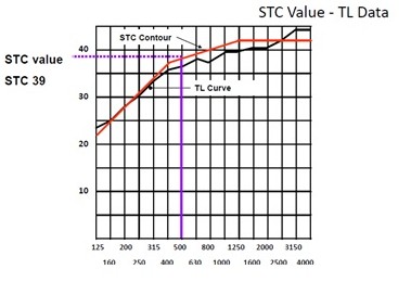
The graph depicted here is a plot of the individual transmission loss values (TL) at specific frequencies taken from an ASTM E90 test. The solid black line is the actual test results. The red line is called the STC contour curve and it is defined within the ASTM standard. The red line is graphically manipulated over the black line until certain ASTM placement requirements are met. Then a vertical line (purple in this case) is drawn vertically up from 500 Hz. The resulting intersection is then the STC value of the tested assembly, a 39 in this case. Some interesting observations can be made from this graph. The first is that the TL is different at each frequency. That implies that the attenuation is not uniform across the frequencies tested. A wall may respond very well at one frequency, and poorly at another. A more important point is that two walls with the same STC may behave very differently at the same frequency. Because of this phenomenon it is well advised to discuss critical conditions with a recognized acoustical engineer.
Another observation is that the tested system appears to let more sound energy through at lower frequencies. This is true for most panel assemblies. Mass is a key factor for reducing sound transmission, especially at low frequencies. Many systems can be acoustically transparent at very low frequencies. The range of frequencies that is evaluated in ASTM E90 coincides with the range of human speech. If the sound source that a designer is trying to control is mechanical or musical where low frequencies are common the STC value alone may not be sufficient. Again, it is recommended enlisting the services of a recognized acoustical engineer.
Structural borne sound is evaluated in floor–ceiling systems. For example, the system must impede the transmission of foot traffic from the upper floor to the lower ceiling. The concept of the test is similar to ASTM E90 in that there is a sound source on one side of the system and the sound levels in the receiving room are measured. The difference is that the sound source is a mechanical tapping device that is placed directly on top of the finished floor. The test method that is used is ASTM E492 Standard Test Method for Laboratory Measurement of Impact Sound Transmission Through Floor-Ceiling Assemblies Using the Tapping Machine. The result of the test is the system’s Impact Isolation Classification (IIC). The IIC is a single number rating system similar to STC, in that the higher the IIC value the better the system is in controlling structure borne sound.
Beyond the scope of this discussion are the other areas of architectural acoustics. Concepts such as sound reflectivity or how sound waves “bounce off” hard surfaces within a given space can have a significant impact on how well a room performs. This reflectivity leads to reverberation, which is how long sound “lingers” within the space. A little reverberation enhances a space, too much reverberation detracts. This reverberation can be controlled through the use of materials that are strategically placed to reflect sound, and other materials are also placed in the space to absorb sound. This type of design is best handled by a qualified acoustical engineer.
For information on specific assemblies the following sources are suggested:
Heat Transfer
Heat transfer is a function of the thermal resistance of the materials that make up the building thermal envelope. The International Energy Conservation Code (2012) defines the building thermal envelope as “The basement walls, exterior walls, floor, roof, and any other building elements that enclose conditioned space or provides a boundary between conditioned space and exempt or unconditioned space.” These individual resistance values (R-Values) are mathematically combined to predict the performance of the assembly.
Heat is a form of energy and is defined as the relative motion of the molecules of a given material. The hotter the material is, the faster the molecules are moving. This heat is measured in British thermal units, or Btu. A single Btu is defined as the amount of heat energy required to raise one pound of water from 63o to 64oF.
There is a directionality to heat transfer. Heat always flows to colder temperatures. From the building envelope standpoint, this means that during winter the heat of the interior space is flowing to the exterior, and conversely in the summer, the warm air on the exterior of the building is flowing to the interior. There are three methods for this heat transfer. They are convection, conduction, and radiation. This paper will primarily discuss conduction.
All common building materials will conduct heat. Therefore, each building material has a coefficient of conductance (k) value that predicts the amount of energy that the material will conduct. The units for this coefficient are Btu per hour, per square foot of material, per inch thickness of material, per degree Fahrenheit. The total heat that will pass through an assembly (the combination of individual building materials each with its own coefficient of conductance) is termed the “coefficient of heat transmission.” This value is expressed as Btu per hour, per square foot, per the degree Fahrenheit temperature difference between the air on one side of the assembly to the air on the other. This value is called a “U” value of the assembly. “Thermal resistance” of a material or assembly is the more common term that is used. Mathematically the thermal resistance, “R,” of a material is the reciprocal of its heat transfer coefficient, which is 1/k, 1/C, 1/U. The higher the “R-value” of a material is the greater its resistance to the transfer of heat.
The above is taken from Navigating Uncharted Waters: Understanding the Energy Codes and
How They Impact the Role of the Contractor. (A research paper prepared for The Foundation of Wall and Ceiling Industry).
Moisture Migration
One of the more important factors in the design of the exterior envelope is controlling water migration through the walls, the roof, and the foundation. Water-resistive membranes, flashing, and sealants are typically used to control water in its liquid state. Water in its vapor state can be a little more challenging, and is a natural occurrence in the air we breathe. The common term is “humidity.” Building materials can either allow or resist the passage of water vapor through them. They all have what is termed a “perm rating,” or a rate in which they allow vapor transmission. Similar to how heat flows from hot to cold, moisture travels from areas of high vapor pressure (high humidity) to areas of low vapor pressure. In a very real sense, water is driven through an exterior wall from the hot moist outside air to the relatively cool dry inside air. At the same time as the vapor is migrating through the wall the temperature is dropping through the existence of insulation. In a poorly designed or erected wall the temperature can drop to what is called the “dew point,” which is where the water will convert to its liquid state, similar to beads of water on a cold soda can. If this condensation occurs inside the stud cavity it will have catastrophic consequences. Therefore a good exterior envelope design includes a dew point analysis, and attention to detail in the construction phase is equally critical.
The above is taken from Navigating Uncharted Waters: Understanding the Energy Codes and How They Impact the Role of the Contractor. (A research paper prepared for The Foundation of Wall and Ceiling Industry).
Expanding on the concept of the water resistive membrane for exterior applications the current International Building Code (2009) calls for a Water Resistive Barrier to be installed behind the exterior veneer (see Section 1403.2). In the case of a framed exterior wall the idea is to restrict the potential for water entering the stud cavity. The code further interprets the water resistive barrier to be #15 building paper or equivalent. Some recognized barriers are 1. Asphalt saturated papers and felts that meet ASTM D226 Standard Specification for Asphalt Saturated Organic Felt Used in Roofing and Waterproofing Type I, 2. Polymeric sheets, 3. Fluid applied barriers, and 4. Rigid board barriers. The proper design of a water barrier must include flashing, weeps, and a drainage system to allow for any water in its liquid state to exit from the exterior wall.
The Tile Council of North America (TCNA) provides guidance in what is termed “membranes” in tile applications. These membranes are used in either interior or exterior applications. In the 2013 Edition of the TCNA Handbook for Ceramic, Glass, and Stone Tile Applications there are definitions of the various types of membranes and where they should be used in interior, exterior, wall and floor applications that call for a tile finish. The “Membrane Selection Guide” defines cleavage membranes, vapor retarder membranes, waterproof membranes, and low perm waterproof membranes as they relate to moisture control within tile installations. The American National Standards Institute (ANSI) Standard that covers these materials is ANSI A118.10 Load Bearing, Bonded, Waterproof Membranes for Thin-Set Tile and Dimensional Stone Installation.
The ASTM Standard that applies to vapor permeance is E96 Standard Test Methods for Water Vapor Transmission of Materials. There are two methods in which permeability is measured. In the first method the sample to be tested is installed tightly to a cup that has a desiccant (a material that absorbs water). This cup is this placed in a controlled environment where the temperature (73oF) and Relative Humidity (50% RH) is maintained. In the second method the sample to be tested is installed over a cup of liquid water, and then placed in the same controlled environment. In both cases, the permeability of the tested material is then obtained by the rate of change found in the sample’s mass.
Another important test for building materials is a test that measures the amount moisture that a material will absorb. Long term moisture absorption in a material can be bad for it may cause degradation of the material itself, or the materials adjacent to it. In some cases, such as moisture migration through an exterior wall system, having a material in place that absorbs water in the system may be good. This material can help lessen the potential for the development of a dew point and subsequent condensation in a stud cavity. A common water absorption test for gypsum panels is found in ASTM C473 Standard Test Methods for Physical Testing of Gypsum Panel Products. In this test a sample panel is immersed in water for a period of time, 2 days, and the percentage increase in weight is measured.
Structures
Wall Framing
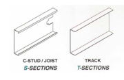
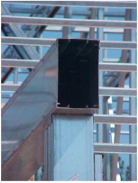
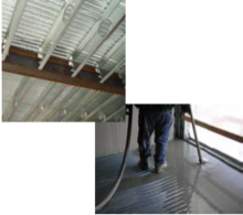
Framing members are typically spaced at 16 or 24 inches on center, with spacing variations lower and higher depending upon the loads and coverings. Wall members are typically vertical lipped channel “stud” members, which fit into channel “track” sections at the top and bottom. The sketches to the right depict the common stud, joist, and track profiles. The track sections are typically fastened to a concrete deck with power driven fasteners. The photograph to the right shows a track attached to a concrete deck. In the track a stud has been installed. In structural applications the stud must be mechanically attached to the framing. In non-structural applications the stud is not attached to the track.
In structural applications, headers are installed over any openings such as doors and windows. There are several options to be considered with the one shown at the left as a “boxed header.” This is where C-Stud/Joists members are installed with the open side facing each other. The number of C-Stud/Joist members, their steel thickness, and depth of the member will vary with the openings that they must span.
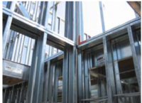
In multi-floor applications it is important that all the wall framing studs align vertically, thus creating a continuous load path from roof to foundation. Notice in the photograph on the right how all the studs are installed from one floor to the next on top of each other. To resist rotation of the studs, lateral bracing is used. This is typically done with channel bracing that is installed in the cavity of the wall by running the channels through the convenience holes located in the web of the C-Stud member. In non-structural applications gypsum panels provide the required bracing.

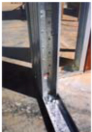
The photograph on the left illustrates how the lateral bracing should be installed. The cold-rolled steel channel is running horizontally in the cavity of the wall. It runs through a punch-out in each stud. There is a small clip angle that is used to mechanically attach the channel to the stud.
Lateral bracing is one option for accommodating wind bracing or “shear walls.” Unlike the bracing described above, which runs horizontally, this bracing is installed in an “X” configuration. Other options include proprietary panels. In mid-rise construction, the exterior wall framing is usually installed in a “balloon” framing configuration. This is where the exterior wall framing runs continuous by the floor framing. This is detailed in the Exterior Systems Details of this site.
Floor Framing
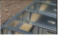
Similar configurations are used for both floor joist and rafter assemblies, but in a horizontal application for floors, and a horizontal or sloped application for roof framing. Accessories of the framing system include fasteners and connectors, braces and bracing, clips and connectors. The photograph at the right illustrates a floor joist (C-Stud/Joist profile) installed directly over a load-bearing stud. A track section is used to cap the joists and tie them altogether. This is an example of platform framing that is the framing of choice for low-rise conditions. In the photograph below, there are web-stiffeners installed where the joists bear on the wall framing. Another way to do the floor framing is to use a steel floor truss that is made up of C-Stud/Joist members. There are many available truss manufacturers that design and fabricate trusses.
There are several options of floor systems that can be used over the joists. Plywood is common for combustible construction. In non-combustible applications, one can use precast concrete, poured-in-place concrete, non-combustible panels, or corrugated steel deck (minimum 22 gauge) and a cementitious topping. The two photographs to the right show a corrugated steel deck (shown from below) and a mechanic pouring the topping over the deck.
Roof Framing
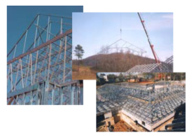
Roof framing members can either be C-Stud/Joists installed in a common rafter style or trusses can be fabricated using C-Stud/Joist members. As with floor truss systems, there are many local fabricators available that design, build, and supply the trusses. The three photographs to the right show both types of framing. The crane in the center photograph illustrates how panelization of framing systems can be used to facilitate installation. Panelization offers many benefits such as reducing the construction schedule and increasing quality control over conventional built-in-place techniques.
Non-Structural Framing-Limiting Heights
The strength and stiffness of any cold-formed steel framing member is determined by three things. They are the thickness of the steel, the material properties of the steel, and finally the geometric properties provided by the framing member’s profile.
 Material thickness:
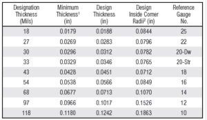
 Cold-formed steel is formed from relatively thin sheets of steel. The chart shown here is taken from the Steel Framing Industry Association’s
Technical Guide, and provides the basic thicknesses that are available. The steel is measured in “mil” thickness therefore the basic interior non-loadbearing stud is 18 mils. The minimum thickness of the steel, measured in inches is 0.0179 inch. This is the thickness of the steel itself without a protective coating. The roll-forming process in steel does not provide a uniform thickness of steel within what is termed a coil of steel. The coil as shown here arrives at a framing fabricator facility ready to be slit and formed into individual stud, joist, or track profiles. The thickness of steel will vary within this coil. To accommodate this variance, the thickness 0.0179 inches represents the minimum thickness acceptable. There is a note on the bottom of the table that states “Minimum thickness represents 95% of the design thickness and is the minimum acceptable thickness delivered to the jobsite based upon Section A2.4 of the AISI S100-07 Specification.”
Material properties: Steel is considered a ductile or elastic material. Therefore an important material property to consider when designing with cold-formed steel framing members is steel’s yield strength. Steel will deform under an applied tensile load. When that load or stress is released, the steel will return to its original shape. At some load level the steel will not return to its normal shape and permanent deformation will occur. Yield strength is then defined as that threshold stress where permanent deformation occurs in an otherwise ductile material. This is a critical factor when designing in cold-formed steel framing, and is measured in pounds per square inch. Because the value can be fairly high the values are published where “1 kip” equals 1000 pounds. Common yield strengths used in cold-formed steel framing are 33 ksi (kips per square inch) and 50 ksi.
 Geometric Properties:
 The bending of a flat sheet of steel increases its ability to withstand an applied load. Consider that a flat piece of paper cannot stand up, yet it can when folded in half. Therefore the final profile of a cold-formed steel member is equally important. The two most important geometric, or “section” properties to consider is a profile’s “Moment of Inertia” with the units of inches to the fourth, and “Section Modulus.” The units of Section Modulus are inches to the third power. The moment of inertia, symbolized as Ix, predicts a profile’s stiffness or ability to resist deflection. The deeper a member, the more it can resist deflection. A 6” deep stud is stiffer than a stud that is 1-5/8” deep. The section modulus, symbolized as Sx predicts a profile’s strength. It determines, along with the steel yield strength how much load a profile can take until ultimate failure. A final geometric consideration of a profile is its web depth. As the web of a stud gets larger so does the potential for web buckling. This is a factor when analyzing end reaction and shear capacity. The SFIA
Technical Guide for Cold-Formed Steel Products provides the section properties for all the profiles.
Lateral load on interior partitions: For many years the accepted design load for interior partitions was 15 psf. It was based on the assumption of loads imparted on an interior partition as a result of an open window. This requirement was based on work done in the 1940s by the Building Research Advisory Board (BRAB). This board was part of the National Research Council. In 1967 a code change was approved by ICBO (International Council of Building Officials) for the Uniform Building Code to reduce the load to 5 psf. This change was based on work done by Wiss, Janny & Elstner that was commissioned by the Gypsum Association. A 5 psf uniform load is still the design load and referenced in both the Gypsum Association GA 600 Fire Resistance Design Manual and ASTM C754 Standard Specification for Installation of Steel Framing Members to Receive Screw-Attached Gypsum Panel Products.
 Limiting heights tables:
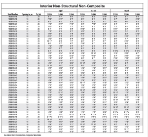
 The height table here provides the designer with information of how tall a wall can be designed with a given non-structural stud. The table is taken from the Steel Framing Industry Association’s published
Technical Guide for Cold-Formed Steel Products. The tables are based on a uniform lateral load only. It is not meant for when the framing member must have the capacity for loadbearing (axial load) conditions. Other tables in the guide provide information on combined lateral and axial loads. The table evaluates each standard stud profile at 12, 16, and 24 inches on center. It also limits deflection (a function of the profiles moment of inertia) to l/120, 1/240, and l/360. Deflection should be determined based on the intended finish in order to limit the potential for that finish material to crack. The table also looks at heights limited by bending stress and end reaction shear (web buckling). Bending stress is measured by the yield strength of the steel and the profiles section modulus.
These wall heights are determined by tests following the procedures required by AC86 - Acceptance Criteria for Determining Limiting Height of Composite Walls Constructed of Gypsum and Steel Studs. This procedure was established by the International Code Congress – Evaluation Services, ICC-ES.
The tables published today by the SFIA for interior non-load bearing partitions only evaluate heights based on the stud properties alone, or are labeled as “non-composite.” Gypsum panels installed on both sides of a partition effectively stiffen the wall. This contribution is recognized in “composite” tables. What is important to understand is that the test procedure for determining composite wall heights requires that the panels are fastened around the perimeter of the partition. That means that the composite tables are not to be used when the gypsum panels stop above a suspended ceiling and the studs are not covered from that elevation up to structure. For that reason, some manufacturers have tested and published values for that condition. This is called “fully braced” and assumes lateral bracing is provided by other means above the plane of the ceiling.